OH-6 Cayuse

The Hughes OH-6 Cayuse ("the Loach") was a light observation helicopter used by the US Army in the Vietnam War and other armed conflicts. Being part of the aerial cavalry, it was a high-performance and easily maintained helicopter. It was well armed, small and agile, being ideal for riverine support operations in the jungles of Vietnam. The OH-6A was the first production version. Hughes also developed a civilian version, which was the Model 500.

The first prototype, the YOH-6, made its maiden flight on February 27, 1963. The first batch of OH-6As was delivered to the US Army in September 1965 and it became fully operational in September 1966. It would be sent to Vietnam in 1968. This helicopter was nicknamed "the Loach" for the LOH designation. In service with the US Marine Corps, it operated together with the AH-1G Cobra as a team; the Loach designated targets using color smoke rockets and the Cobra attacked them with its lethal firepower. Later, in other armed conflicts, it would also be used for special operations for insertion of Special Forces behind enemy lines.

Technical Characteristics

The Hughes OH-6 Cayuse was a light helicopter, with a teardrop-shaped fuselage. The tailboom tapered towards the rear end, which had three fins. The main rotor had four blades, while the tail rotor had two. Each of the main rotor blades was attached to the one opposite by 15 flexible stainless steel straps. It was powered by one Allison T63-A-5A turboshaft engine, which put out 320 horsepower.

The OH-6 Cayuse had excellent control response, with little vibration at high speeds. The main rotor had a small diameter, which was useful among the tree-tops of Southeast Asia jungles. Due to being very maneuverable, it was also used for support and attack missions and medical evacuation. The AH-6G was the attack version of the Loach, while the MH-6H variant had two long planks on the sides ("people planks"), which was for Special Forces insertion.

Specifications (OH-6A)

Type: light observation helicopter

Main Rotor Diameter: 8 m (26 feet, four inches)

Length of Fuselage: 7 m (23 feet)

Height: 2.48 m (8 feet, 2 inches)

Power Plant: one 320-HP, Allison T63-A-5A turboshaft engine

Maximum Speed: 241 km/h (149 mph)

Range: 611 km (379 miles)

Service Ceiling: 4,815 m (15,800 feet)

Accommodation: one pilot and one observer, plus up to four passangers.

Armament: one 7.62mm XM27 machine gun, with provision for two 7.62mm M60 machine guns. The AH-6G version had two rocket launchers.

 Below, the OH-6 Cayuse in Japanese service

Read More...

M5 Light Tank

The M5 light tank was used by the US Army and Marine Corps during World War II. It made its combat debut with the 70th Tank Battalion in North Africa in November 1942. However, it would prove to be poorly suited for the European Theater, due to its thin armor and an underpowered 37-mm gun. This is the reason it would be replaced by the M24 Chaffee. The M5 only remained viable and effective in the Pacific war. Thus, the US Marine Corps used the M5A1 in small numbers in the last campaigns of the Pacific Theater. It saw combat action on Saipan, Tinian, and Okinawa Island.

The tank in 1943, during WW2


Technical Description

The M5A1 light tank had a much-improved and larger turret than its predecessor's; the M3 Stuart. This new turret had additional room in the rear of it for the radios. The hull was also longer, with an escape hatch on the floor behind the co-driver. The fuel tanks were re-located to the rear corners of hull, which had thicker armor at the sloping front (glacis). The tank rode on four road wheels contained in two bogies, with the sprocket drive wheel in front and the idler in the rear.

Compared to other light tanks that preceded it, the M5A1 had a stronger power plant as it was driven by a twin Cadillac V-8 gasoline engine, which delivered 220 horsepower and 488-lb of torque at 1,200 rpm. Each engine had its Hydramatic transmission, with four speeds forwards and one reverse. It was equipped with two driveshafts, which went forward to a two-speed synchronizing transfer unit bolted to the front differential. Until 1944, 6,810 units were produced by Cadillac and Massey Harris.

Specifications

Type: light tank

Weight: 15.20 tons

Length: 4.84 m (15 feet, 10.5 inches)

Width: 2.29 m (7 feet, 6 inches)

Height: 2.57 m (8 feet, 5 inches)

Power Plant: two 346ci Cadillac, V-8, gasoline engines.

Maximum Speed: 58 km/h (36 mph)

Range: 161 km (100 miles)

Armament: one 37-mm M6 gun;  three 7.62-mm (.30-cal.) machine guns.

Crew: 4

Below, the M5A1 light tank on exhibition.


Below, the 5A2 version as part of a private collection driving on a country road.


Read More...

M24 Chaffee

The M24 Chaffee was a light tank in service with the US Army during the Second World War and the Korean War. Designed by Cadillac in 1943, it was introduced into active service in 1944, replacing the M5 Light Tank. Although it did not see combat action in Normandy, as it arrived in Europe in November 1944, it did take part in the Battle of the Bulge, which began the following month. It was the last light tank built by United States during the Second World War.

The main asset of the M24 Chaffee was its 75-mm gun. For such a powerful weapon, the engineers had to design an entirely new turret to accommodate it. The turret was drastically different from the M5's and other previous tank turrets. The Chaffee was powered by two Cadillac Model 44T24, V-8 gasoline engines, which were mounted at the rear of tank. Each of them produced 220 horsepower. The 24-volt generators were mounted in front of engines block, with a driveshaft under the intake manifold. This shaft drove the radiator fan. The engines were tied together with a two-speed transfer case located on the floor under the rear of turret.

Below, front view of the M24 Chaffee light tank


The driver and assistant sat in front, on each side of the differential, with dual driving controls. The assistant driver operated a .30-caliber machine gun in a ball socket-type bow mount. The hull of the Chaffee was of all-welded steel plate. On the hull front (glacis), there was a large access steel plate hatch, which served as an access to service or replace the differential. The hull rode on five dual-tired sets of road wheels per side, with torsion bar suspension. The drive sprocket was located at the front, with the adjusting idler wheel at the rear. The tracks were single-pin steel, with a 16-in-wide center guide.

Specifications

Type: light tank

Weight: 18.37 tons

Hull Length: 5 m (16 ft, 4.5 in)

Full Length (with gun):  5.49 m (18 ft)

Width: 2.95 m (9 ft, 8 in)

Height: 2.48 m (8 ft, 1 in)

Power Plant: two Cadillac Model 44T24, V-8 gasoline engines.

Maximum Speed: 56 km/h (35 mph)

Range: 161 km (100 miles)

Armament: one 75-mm T13E1 gun; one .30-caliber machine gun in front hull and a 12.7-mm (.50-cal) machine gun on turret.

Crew: 5

Below, an US Army's armor unit composed of M24 Chaffee tanks in Europe in December 1944.

A color photo of the Chaffee. Rear andside view.


Below, the hull glacis showing the location of the .30-caliber machine gun operated by the assistant driver.


Read More...

Leopard 1

The Leopard 1 was a Cold War main battle tank used by the German Army from 1963 to 1993, being replaced by the Leopard 2. It was designed and developed by the German firm Porsche and manufactured by Krauss Maffei as a replacement for the American-made M60 Patton, which had been until then the Bundeswehr’s main battle tank. Its prototype was produced and tested in 1962, entering service the following year. It was manufactured in five models: the Leopard 1A1, 1A2, 1A3, 1A4, and 1A5.

Although it is no longer deployed by the German Army, it is still in service with the Brazilian, Canadian, Chilean, and Turkish Army. It saw combat action with the Canadians from 2006 to 2010 in Afghanistan in the Leopard C2 version. As of 2023, the German federal government and the firm Krauss Maffei authorized the shipping of 178 Leopard 1 tank to Ukraine, plus 14 Leopards 2 tanks to reinforce the Ukrainian Army’s armored units to fight against the Russian Ground Forces.

Technical Characteristics

The Leopard 1 features a 105-mm rifled gun, which is based on the British Royal Ordnance L7 that had been used on the Centurion Mark 5 tank. It has an effective maximum range of 2,000 m. It is fitted with a gun stabilization system, which makes it possible for the tank to fire as it rolls, no matter how rough the terrain is. It is also equipped with infra-red search light. The tank is protected with conventional steel armor, but the tower is reinforced with additional spaced armor. Face-to-face with a Russian T-72B3 tank, the Leopard 1 has no chance; it would be suicidal.

Specifications

Type: Main Battle Tank

Weight: 40 tons

Hull Length: 8.17 m

Full Length: 9.55 m

Width: 3.37 m

Armor: steel

Powerplant: 850 HP, 10-cyl. diesel engine.

Maximum Speed: 65 km/h

Range: 550 km

Below, the Leopard 1A3 in 1980 in northern Germany.


The Leopard 1A2 version in 1971


Below, the Leopard 1 during NATO military exercises.


Read More...

Hawker Hunter

The Hawker Hunter was a British fighter and interceptor jet aircraft in service with the Royal Air Force during the Cold War. Fast and maneuverable, it represented a major improvement over the Gloster Meteor and the de Havilland Vampire. As a result, it was popular with the pilots and had almost flawless handling qualities, with few limitations. Its maneuverability had a lot to do with its swept wing design.

The prototype of the Hawker Hunter, the P.1067, took to the air for the first time on July 20, 1951. It was powered by one Rolls Royce Avon 103 axial-flow turbojet engine. After a long period of flight tests and technical corrections, it was officially introduced into service in July 1954, with the delivery of the first batch of 113 aircraft. It would be built in large numbers, with a total of 1,972 units, in several versions; from the F.Mk 1 to the F.Mk 6 variant, as well as two two-seat trainers; the T.7 and T.8.

The Hunter flew combat sorties during the Suez Canal Crisis, in 1956, as escort for the English Electric Canberra bombers. It was also used by the RAF during the 1962 Brunei Revolt, to provide fire support to British ground forces.

Technical Description

The Hawker Hunter was a single-seat, single-engine monoplane, which was built with an all-metal semi-monocoque fuselage. It had swept mid-wing, whose leading edge swept back at 35 degrees. The tail assembly horizontal stabilizer also swept back at the same angle. The F.Mk-5 version was powered by one Armstrong Siddeley Sapphire 101 turbojet engine, which produced 6,500-lb of thrust. The engine had two triangular air intakes, which were located on fuselage sides in wing roots. As any modern jet aircraft, the landing gear was retractable.

Specifications (F.Mk-5)

Type: single-seat fighter/interceptor

Length: 13.98 m (45 feet, 10 inches)

Wing Span: 10.29 m (33 feet, 9 inches)

Wing Area: 33.42 m2 ( 360 sq. feet)

Height: 4 m (13 feet, 2 inches)

Power Plant: one Armstrong Siddeley Sapphire 101 turbojet engine.

Maximum Speed: 1,027 km/h (638 mph)

Range: 689 km (428 miles)

Service Ceiling: 15,240 m (50,000 feet)

Armament: four 30-mm Aden cannons

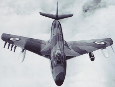
Below, the Hawker Hunter F.Mk 4 in flight

The F.Mk 1 in 1957.


Read More...

Handley Page Victor

The Handley Page Victor was a long-range, strategic bomber used by the British Royal Air Force during the Cold War years. It was a fast subsonic aircraft, which belonged to the trio of Britain's V-bombers, the others being the Avro Vulcan and the Vickers Valiant. It had a large bomb-bay capacity as it could carry forty eight 1,000-lb conventional bombs, or two Blue Steel nuclear-tipped stand-off missiles. For defense, it was equipped with top-secret electronic counter-measures system.

The Handley Page Victor performed its maiden flight on December 24, 1952. From then on, it would have a protracted development period, finally being introduced into service in April 1958. It was in many ways a very advanced aircraft; for protection from interceptors attack, it was fitted with one rear-facing radar in the tail cone. Handley Page built 86 Victors in three basic variant; the B.Mk.1, B.Mk.2, and B.Mk.2R, which was a reconnaissance conversion. The K.1 and K.2 versions were in-flight refueling tankers, which was the role it had been relegated to after the Cold War. During the 1991 Gulf War, it flew many sorties to refuel British combat aircraft.

Below, the prototype WB771 in flight in early 1953.


Technical Description

The Handley Page Victor was a four-engine, jet monoplane. It was fitted with crescent-shaped mid-wing and all-metal fuselage. The wing had a sweep of 48.5 degrees inboard (at its root), 35 degrees at the center, and 27 degrees at the outboard section, thus, giving it a crescent shape. Only the outboard section had leading-edge slats, which was designed to improve low-speed handling. The tail assembly vertical stabilizer (fin) was short and fitted with an all-moving horizontal stabilizer (tailplane), which was mounted on top and swept at 45 degrees. The B.Mk.1 version was powered by four Rolls Royce Conway turbofan engines, which were buried in the wing roots.

The maximum diameter of fuselage was 3 m (9 feet, 10 inches) across. Much of the center of fuselage was taken up by the massive bomb-bay. There was a pair of airbrakes on the rear fuselage; this portion of aircraft also contained a freight compartment and fuel tanks. Two large bulged pods in the wings held additional fuel for long-range flights. The five-man crew cabin was large and comfortable, with the two pilots sitting at the front side by side, with the rest of crew sitting behind on same level. However, only the pilots sat on ejector seats; the rest could try jumping out.

Specifications (B.Mk.1)

Type: long-range strategic bomber

Length: 35 m (114 feet, 11 inches)

Wing Span: 36.57 m (120 feet)

Wing Area: 241.30 m2 (2,597 square feet)

Height: 8.57 m (28 feet, 1 inch)

Power Plant: four 20,611-lb-thrust Rolls Royce Conway RCo.17 Mk 201 turbofan engines, and two de Havilland Spectre rocket motors.

Maximum Speed: 1,037 km/h (645 mph), or Mach 0.98

Range: 6,500 km (4,039 miles)

Service Ceiling: 16,765 m (55,000 feet)

Crew: 5

Armament: forty eight 454-kg (1,000-lb) conventional bombs, or Blue Steel stand-off missiles.

Below, the Victor right after take-off in 1973

The B.Mk.1 version parked at a NATO military base in 1962

Below, the B.Mk.2 variant in flight.


Three Victor K.2s during the Gulf War.


Read More...

Grumman OV-1 Mohawk

The Grumman OV-1 Mohawk was an American reconnaissance and liaison aircraft used by the US Army during the Vietnam War. However, in this armed conflict, this reliable airplane flew also ground-attack missions as it had underwing pylons to carry rockets and bombs. Although it was relatively slow, it was a light and very maneuverable aircraft. It was the first turboprop-powered airplane to enter the US Army inventory.

The Grumman OV-1 Mohawk had been designed in 1957 in answer to an US Army's requirement, which called for an aircraft that was capable of short take-off and landing (STOL) from rough airfields. This new plane also had to be able to carry observation equipment of different characteristics. The prototype, the YOV-1A, made its maiden flight on April 14, 1959, and it was introduced into US Army service in October 1959 as the OV-1A. The original company designation of this aircraft was G-134.

Below, the YOV-1A prototype in flight during tests.


Technical Characteristics

The Grumman OV-1 Mohawk was a two-seat, twin-engine monoplane. It was fitted with straight, cantilever mid-wing, with full-span leading-edge slats and large trailing-edge flaps. The tailplane assembly was composed of a swept-back horizontal stabilizer, with a 25 degrees sweepback, and triple fin, with three rudders.

The Mohawk had an all-metal fuselage, which was equipped with two airbrakes, one on each side of tail fuselage. The cockpit was large and comfortable, with the pilot and observer seated side by side. The OV-1A variant was fitted with cameras for photo reconnaissance, while the OV-1B version was equipped for radar reconnaissance, using a sideways-looking airborne radar. The OV-1C had a camera and infrared sensors, while the OV-1D combined the equipment of all the earlier versions.

Specifications (OV-1D)

Type: two-seat reconnaissance and liaison aircraft

Length: 12.50 m (41 feet)

Wing Span: 14.63 m (48 feet)

Wing Area: 33.45 m2 (360 square feet)

Height: 3.86 m (12 feet, 8 inches)

Power Plant: two Textron Lycoming T53-L-15 turboprop engines, each one delivering 1,100 horsepower.

Maximum Speed: 507 km/h (315 mph)

Range: 1,642 km (1,020 miles)

Rate of Climb: 716 m/min (2,350 feet per minute)

Armament: rockets; bombs

Crew: 2

Below, the US Army Mohawk flying over California.


The OV-1C in flight over the West Coast.

Below, the OV-1B on a military base in Vietnam in 1966. The pod under the fuselage houses a side-looking radar.


Read More...

Grumman F11F Tiger

The Grumman F11F (F-11) Tiger was a carrier-borne, day fighter used by the US Navy during the Cold War.  It was the first supersonic fighter aircraft to enter US Navy service. Being introduced in 1957, its career was relatively short as it was phased out from carrier operations in 1961, being relegated as an advanced pilot trainer from then on, with the new designation F-11. The reason for this was the appearance of the more capable Vought F8U Crusader. Thus, it would not see combat action in Vietnam.

The prototype of the Grumman F11F Tiger, the XF9F-9, first flew on July 30, 1954. Almost three years of intense trials had gone by, when it entered fleet service with the Attack Squadron One Five Six (VA-156) at NAS, Moffet Field, California, in March 1957, as the F11F-1. Thus, delivery occurred two years later than it had originally been planned. Although it had advanced features, which made it capable of flying at supersonic speeds, it lacked a powerful air-to-air radar. Only 201 aircraft would be produced between 1954 and 1959 in two variant; the short-nosed and the long-nosed Tiger.

Below, a photo of the F11F-1 in flight (belly view), carrying four Sidewinder air-to-air missiles.


Technical Description

The Grumman F11F was a single-seat, single-engine, carrier-capable fighter. It was powered by one Wright J65-W-18, afterburning, turbojet engine, which delivered 7,450-lb of thrust. The engine was of the axial-flow type and it incorporated 13 compressor stages, and two turbine stages rotating clock-wise (when viewed from the rear). This power plant enable this aircraft to fly at the maximum speed of Mach 1.2 at 35,000 ft of altitude. The landing gear was of a retractable tricycle type, with all wheels retracting into the fuselage.

Technically, the Tiger was a cantilever mid-wing monoplane, built with an all-metal fuselage. It was fitted with swept wings, with a 30 degrees leading-edge sweepback and a 6.5% thickness/chord ratio. It had leading-edge slats and trailing-edge flaps over the whole fixed portion of wings, whose tips were manually hinged for carrier stowage. The all-metal fuselage had three finger-type speed brakes located on belly of aircraft. Meanwhile, the tail unit was made up of a fixed fin, with rudder, and low-mounted all-flying horizontal plane, with a slight dihedral.

Specifications (F11F-1/F-11A)

Type: carrier-based day fighter

Length: 14.31 m (46 feet, 11 inches)

Wing Span: 9.64 m (31 feet, 7 inches)

Wing Area: 23.23 m (250 square feet)

Height: 4 m (13 feet, 3 inches)

Power Plant: one Wright J65-W-18 turbojet engine

Maximum Speed: 1,211.8 km/h (753 mph)

Range: 2,044 km (1,267 miles)

Service Ceiling: 12,770 m (41,900 feet)

Armament: four 20-mm Mk-12 cannons; up to four underwing AIM-9 Sidewinder missiles

Below, an F11F-1, lengthened nose variant, in 1958. You can see its speed brakes on the underside of fuselage.


The Tiger in flight, with refuel probe extended.


Below, the first production aircraft in 1957.

Read More...